function FlattenCSpline(const pts: TPathD): TPathD;
This function converts CSpline points into a flattened path. It loosely approximates the 'S' command inside the 'd' property of an SVG path. In essence, the 'pts' array represents a series of control points and coordinates that make up a series of joined cubic bezier curves.
The first four coordinates of the spline represent the starting point, two control points, and end point of the first sub-curve (just like a cubic bezier curve). Subsequent pairs of points represent the second control point and the end point for following sub-curves. Only two points are required for all but the first sub-curve because the end point of a preceding sub-curve becomes the starting point of the next sub-curve, and the second control point of a preceding sub-curve, once reflected across its end point, becomes the derived control point for the next sub-curve.
uses
  Img32, Img32.Fmt.PNG,
    Img32.Vector, Img32.Draw;
...
var
  img: TImage32;
  path: TPathD;
  pts: TPathD;
  ghostPt: TPointD;
begin
  img := TImage32.Create(256,256);

  //CODE FOR (BLUE) QSPLINE OMITTED

  //create and draw a RED CSpine path
  pts := MakePathI([50,200, 40,160,
    90,160, 80,200, 120,240, 110,200,
    150,160, 140,200, 180,240, 170,200,
    210,160, 200,200]);
  path := FlattenCSpline(pts);
  DrawLine(img, path, 8, clRed32, esRound);

  //show where the 'pts' are too
  for i := 0 to high(pts) do
    DrawPoint(img, pts[i], 3, clNavy32);

  //and show the derived control points
  i := 2;
  while i < high(pts) -1 do
  begin
    ghostPt := ReflectPoint(pts[i], pts[i +1]);
    DrawPoint(img, ghostPt, 3, clSilver32);
    inc(i, 2);
  end;

  img.SaveToFile('splines.png');
  img.Free;
end;
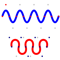
In the image below the red curve is a CSpine. The dark navy dots indicate the user defined control and end points, and the pale gray dots indicate virtual control points (ie derived from preceding control points).
FlattenCBezier, FlattenQSpline
Copyright ©2010-2023 Angus Johnson - Image32 4.8 - Help file built on 16 Apr 2025